f2022-public-labs
Lab 2: Interrupts
- Lab 2: Interrupts
- 1. Introduction
- 2. Instructional Objectives
- 3. Background: Interrupts and Event-Driven Programming
- 4. (100 points) Experiment
- 5. (Bonus 20 points) Observations and Adjustments
1. Introduction
Microprocessors consistently follow a straight sequence of instructions, and it is likely that you have only worked with this kind of programming until now. In this experiment, you will configure a microprocessor to handle exceptional events. These events will be generated in an expected manner, but the principles are the same for failures, faults, and other unexpected events. These events will invoke Exception Handlers that you write. These Exception Handlers will efficiently respond to events only when needed and will not run continually.
2. Instructional Objectives
- Learn about the SysTick and External GPIO interrupts (EXTI) of a microcontroller
- Implement Interrupt Service Routines
3. Background: Interrupts and Event-Driven Programming
An exception handler (or interrupt service routine) is a hardware-invoked subroutine. There are many types of events that can be configured to generate exceptions. When these events constitute failures, this type of programming is valuable for error handling and fault recovery. More often, we create exception handlers to deal with things we want to occur occasionally, and that we do not want to force the microprocessor to continually poll (check on repeatedly). This is called event-driven programming. Here, the event in question is expected to be handled quickly and only occasionally.
This is, arguably, the most important rule about interrupt handlers. They should be short, do only what is essential, and return as soon as possible.
4. (100 points) Experiment
In this lab experiment, you will use the simplest interrupt source that can be configured, the SysTick interrupt. You will also use the interrupt source that is most easy to understand, the external GPIO interrupt. Although it is conceptually simple (press a button to invoke a subroutine), the steps needed to configure it are numerous, and they are difficult to accomplish by a novice reading of the manual. You will do these things in steps that are carefully documented. Later, you will be able to modify the system to do other interesting things.
You should use the same external parts that you wired to the microcontroller in lab 5. In particular, the debounced buttons connected to PB0 and PB4 will be important for this lab.
Download the lab 6 template from lab website and import it into System Workbench like you have done for previous labs. Noted you might need to set up the debug configuration manually like in lab 5, make sure to follow steps in lab 0.1 to do this.
4.1 Setting up a long-running program
In this experiment, we want to model a case where the CPU has something to work on rather than just sit idly. We’ll do this with the very simple nano_wait subroutine:
.global nano_wait
nano_wait:
    subs r0,#83
    bgt  nano_wait
    bx lr
This function is very carefully timed so that each iteration of the loop takes 83 nanoseconds when the CPU clock is 48 MHz. It’s not particularly useful, but it will keep the CPU busy for a predictable time. In addition, it will be provided in the template in file nano_wait.S with function signature void nano_wait(uint32_t t). If you call it with the value 1,000,000,000 as the first argument, it will return approximately 1 second later.
4.2 (20 points) Implement Several GPIO subroutines
To demonstrate the long-running function as well as the interrupts you will set up for this lab, you will write several GPIO subroutines that will be called in several places. Each of these subroutines is similar to those you wrote for lab 5. Use autotest to ensure they are correct before moving on (make sure you have connected both the UART and JTAG programmer to use autotest).
4.2.1 (5 points) initc
In the template file main.c, implement the initc function that enables the RCC clock for GPIO Port C (without affecting the other clock enable bits in the AHBENR) and configures the appropriate pins as follows:
- 0-PC3 as input pins with the pull down resistor enabled
- PC4-PC9 as output pins
Make sure, for this subroutine and the next one, to change only the pins specified.
Hint: You can use
RCC->AHBENRto access theAHBENRregister and useGPIOC->MODERto access the GPIO port C’sMODERregister. The same mechanism applies to the internal push-down/up resistor configuration.
4.2.2 (5 points) initb
In the template file main.c, implement the initb function that enables the RCC clock for GPIO Port B (without affecting the other clock enable bits in the AHBENR) and configures the appropriate pins as follows:
- PB0, PB2, PB3, PB4 as input pins
- enable pull down resistor on PB2 and PB3
- PB8-PB11 as output pins
4.2.3 (10 points) togglexn
In the template file main.c, implement the togglexn that accepts two parameters which are the GPIO base address and the pin number whose output is to be changed from 1 to 0 or 0 to 1. If I wanted to toggle the PC6 pin, I would call the subroutine as togglexn(GPIOC, 6).
Note: The
togglexnhas signature ofvoid togglexn(GPIO_TypeDef *port, int n).
Hint: You can use the same trick as in
initbandinitcto access theGPIO_TypeDef *GPIO port pointer’s control registers. Use the autocomplete to check the fields of the pointer or look up its definition by usingCtrl + Left Clickon the structure nameGPIO_TypeDefin System Workbench.
4.2.4 Testing
Once you have implemented each of the subroutines described so far, you should run your program to test that it works correctly. The program should slowly blink the blue LED (LD3) connected to PB9. The rate should be approximately .5 Hz.
Uncomment autotest to check that your GPIO configuration subroutines are implemented correctly by typing ‘gpio’ to test initb, initc and togglexn. Once you’re done, comment it out again.
4.3 (20 points) External interrupts
The external GPIO interrupt (EXTI) mechanism allows a GPIO pin to be configured so that a rising edge or falling edge (or both) can trigger the invocation of an interrupt service routine. The steps to do so are intricate, so we will first describe each step briefly, and later expand on each one as you write a subroutine to accomplish it.
- First, write an interrupt service routine with the proper name. There are three separate ISRs to handle all
EXTIinterrupts. One of them handles events configured for pins 0 and 1, the second handles events configured for pins 2 and 3, and the third handles events configured for pins 4 - 15. The handler for SysTick will be given later, but in general, it will be your job to look up the names of ISRs. (Psst, they can be found in startup_stm32.s. You can find them on pg. 217 of the Family Reference Manual, but you’ll have to append _IRQHandler onto the “Acronym” though) . - When any of the three ISRs is invoked, the ISR must acknowledge the interrupt source by clearing its pending bit in the
EXTI_PR(pending register). Unless this is done, the ISR will be immediately reinvoked when it returns. - An
EXTIinterrupt for a particular pin must be associated with a single port. This means that, if pin PA0 is configured to invoke an interrupt, none of PB0, PC0, PD0, PE0, and PF0 can be configured to do so. Pin 0 can only be associated with one port. To make that association,EXTIconfiguration registers in theSYSCFGsubsystem must be written to select the port for a particular pin. - Each
EXTIinterrupt must be configured for a particular pin to respond to the rising edge of an external signal by setting the appropriate bit in theEXTI_RTSR(rising trigger select register). It can also be configured to respond to the falling edge by setting the appropriate bit in theEXTI_FTSR(falling trigger select register). These two registers are independent of each other, so a pin can be configured to invoke an ISR on both the rising and falling edges of a signal. - Each interrupt source must be unmasked so that the
NVICis notified when a pin event is detected. This unmasking is done for a particular pin by setting a bit in theEXTI_IMR(interrupt mask register). Writing a ‘1’ into bit position N unmasksEXTIinterrupt for pin N. - Finally, the
NVICmust be configured to enable one or more of the three interrupts. An interrupt is enabled by writing a ‘1’ to the appropriate position of theNVIC_ISERregister. Unless an interrupt is enabled, theNVICwill leave a posted interrupt in the pending state. It will remain in that state until the interrupt is enabled. Once an interrupt for a pending interrupt is enabled, the ISR is immediately invoked, however it remains in the pending state until whatever generated it is acknowledged. Note that there is a difference between the pending bit in theEXTI_PRregister and an interrupt being in a pending state in theNVIC. That distinction is, perhaps, too complex to study in this lab experiment, but the programming manual offers further clarification.
With this overview complete, you are ready to write the subroutines to make EXTI interrupts work. Implementation and experimentation will make these concepts easier to understand. Let’s take it step by step:
4.3.1 (5 points) An ISR for PB0
Write the EXTI interrupt handler that will be invoked for either PB0 or PB1. You should look up the exact name for it in the startup/startup_stm32.s file and implement it in main.c. You will use this ISR to handle interrupts generated by PB0. It should do two things:
- It should acknowledge the interrupt by writing the value
EXTI_PR_PR0to theEXTI_PR(pending register). TheEXTI_PR_PR0value is a symbol defined for you. ByEXTI_PR, we mean the PR offset from the EXTI configuration register base address. - Call the togglexn subroutine with the arguments that will toggle PB8, which is connected to an LED from last lab’s wiring.
Look at the documentation for the EXTI_PR in section 12.3.6 of the STM32F0 Family Reference Manual. Also note that each of the bits for the EXTI_PR is listed with the behavior rc_w1. If you look at section 1.1 “List of abbreviations for registers” on page 41 of the Family Reference Manual, you will see that rc_w1 means that software can Read as well as Clear these bits by writing a 1. Writing a 0 has no effect. The larger meaning of this designation is that, if you want to clear a single bit when others may be set, you must not do a load-ORRS-store operation since that would clear bits set in the EXTI_PR that you had no intention of acknowledging. Instead, if you want to clear only bit 7 ((1<<7 = 0x80), but leave the 6 bit still set to 1, you need only write the value 0x80 to the EXTI_PR register. Only the 1 bits in the value you write will have an effect.
As is often the case, it take a lot of reading to understand how this works, but the resulting subroutine is fairly simple.
4.3.2 (5 points) An ISR for PB2 and PB3
Write the EXTI interrupt handler that will be invoked for either PB2 or PB3. You should look up the exact name for it in the startup/startup_stm32.s file.
This ISR should look just like the one you created for PB0, except that it has a different name. You will use this ISR to handle interrupts generated by PB2, so it should clear bit 2 of the EXTI_PR register. It should invoke togglexn to toggle pin PB9.
4.3.3 (10 points) An ISR for PB4
Write the EXTI interrupt handler that will be invoked for PB4 through PB15. You should look up the exact name for it in the startup/startup_stm32.s file.
This ISR should look just like the one you created for PB0, except that it has a different name. You will use this ISR to handle interrupts generated by PB4, so it should clear bit 4 of the EXTI_PR register. It should invoke togglexn to toggle pin PB10.
4.4 (30 points) init_exti
Complete the function init_exti. This will require multiple steps with configuration registers in different subsystems, but we’ll walk you through them step by step.
4.4.1 (6 points) Enable the SYSCFG subsystem
First, the subroutine should set the EXTI Configuration Registers (EXTICR1 and EXTICR2) that affect GPIO port B pins 0, 2, 3, and 4 (we will use PB3 later…). Note that these registers are mysteriously part of the SYSCFG subsystem. Like most systems the STM32, an RCC clock must be enabled in order to make the subsystem usable. In this case, it is the SYSCFGCOMPEN bit of the RCC_APB2ENR register.
Think of the APB2ENR register as just like the AHBENR but meant for controlling clocks for a different set of peripherals. You will follow the similar procedure to turn on the bits in APB2ENR like you have done in AHBENR.
Note: The bit to enable the
SYSCFGsubsystem also enables a completely unrelated comparator (see the Family Reference Manual, chapter 15). This is why the bit is namedSYSCFGCOMPEN. We have no idea why this single bit enables the clock for two completely disparate subsystems, or why its use is so obscure. You should look at the documentation for the RCC’sAPB2ENR(Advanced Peripheral Bus ENable Register) if you want to form your own theory.
4.4.2 (6 points) Configure the port-to-pin assignment
Once the SYSCFG subsystem is enabled, init_exti should configure the EXTICR1 and EXTICR2 registers to associate pins 0, 2, 3, and 4 with Port B. (See the documentation for these registers in sections 10.1.2 and 10.1.3 of the Family Reference Manual.) EXTICR1 is a 16-bit register that contains four 4-bit fields. The least significant 4-bit field controls the port association for pin 0. The next most significant 4-bit field controls the port association for pin 1, and so on. Setting the 4-bit field to 0000 associates the pin to port A, 0001 selects port B, 0010 selects port C, and so on. Set the fields of SYSCFG_EXTICR1 and SYSCFG_EXTICR2 so that the EXTI0, EXTI2, EXTI3, and EXTI4 fields are all set to port B (binary value 0001). This will associate each one of these pins to port B.
Hint: You can use
SYSCFG->EXTICRto access all theEXTICRregisters. Since we have 4 of them, this is encoded in an array of length 4. In addition, symbols to configure the ports are already defined, trySYSCFG_EXTICR1_EXTI0_PB, which will set the EXTI0 to port B inEXTICR1.
4.4.3 (6 points) Initialize the RTSR
Next, add to init_exti so that it sets bits 0, 2, 3, and 4 of the EXTI_RTSR register and leaves the other bits unchanged. This will configure pins 0, 2, 3, and 4 to produce an EXTI event on the rising edge of each one of these pins.
The symbols EXTI_RTSR_TR0, EXTI_RTSR_TR2, EXTI_RTSR_TR3, and EXTI_RTSR_TR4 are already defined for you. You should use them to specify the value that gets ORed to the value already in the EXTI_RTSR configuration register.
4.4.4 (6 points) Initialize the IMR
Continue to edit init_exti so that it sets bits 0, 2, 3, and 4 of the EXTI_IMR register and leaves the other bits unchanged. Doing so will unmask the interrupt generation in the EXTI subsystem so that a transition will be sent to the NVIC.
The symbols EXTI_IMR_MR0, EXTI_IMR_MR2, EXTI_IMR_MR3, and EXTI_IMR_MR4 are already defined for you. You should use them to specify the value that gets ORed to the value already in the EXTI_IMR configuration register.
4.4.5 (6 points) Initialize the ISER
Finally, init_exti should write the interrupt numbers into the NVIC->ISER register for an event on pin 0-1. You can look at the the Vector Table (Table 37) on the STM32F0x1 Family Reference to determine what bit position to write to for pins 0-1, or use the symbol to specify the bit position, eg. EXTI0_1_IRQn.
The init_exti subroutine should also enable the interrupt that is raised for an event on pins 2 or 3, as well the interrupt for an event on pins 4 - 15. (Remember that you can use Ctrl-Click to jump to the definition of the symbol for the interrupt number.)
Note: The
NVIC->ISERis an array and you will need to specify the index to access it, i.e.NVIC->ISER[0].
4.4.6 Try it
At this point the init_exti subroutine is complete. You should try it. Press the external buttons connected to PB0 and PB4. Ensure that they cause the LEDs on PB8 and PB10 to toggle each time they are pressed. Button SW3 on the development board is connected to PB2. Make sure that it toggles PB9. This button is not debounced, so it may not be reliable (and that’s not anyone’s fault), but it should still be useful to demonstrate interrupts on PB2.
Once everything works reliably, use autotest to confirm that everything is configured exactly as it should be.
4.5 (30 points) Implement a SysTick handler
The SysTick subsystem is a “core peripheral” of the microcontroller that cannot be disabled, so there is no RCC clock to enable to make it work. It consists of a 24-bit down-counter that automatically reloads a new 24-bit value each time it reaches zero. See the illustration below for the organization of the counter and its control registers. Since they are limited to 24-bit values, the maximum value of the counter and reload value are 2^24 - 1 = 16,777,215.
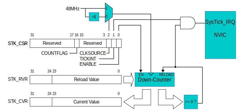
All that is needed to enable the SysTick counter is to set the ENABLE bit in the SysTick Control and Status Register (STK_CSR). Thereafter, the counter decrements once per clock tick. The clock used for the counter is selectable by the CLKSOURCE bit of the CSR. When the CLKSOURCE bit is set to 1, the counter runs at 48 MHz. When CLKSOURCE is set to 0, a divide-by-8 prescaler is used to create a 6 MHz clock for the counter.
The value of the down-counter can be read (or set) at any time by accessing the SysTick Current Value Register (STK_CVR). When the value decrements to zero, the next clock tick will cause a new value to be loaded into the counter from the SysTick Reload Value Register (STK_RVR).
After decrementing to zero, the counter takes one extra clock cycle to reload the new value. The effective frequency of roll-over is then ClockRate / (RVR + 1). For instance, if the 48 MHz clock was selected, and the STK_RVR register was set with the value 11,999,999 then the counter would reach zero exactly four times per second. We won’t use the SysTick subsystem for anything else in this course, but you should get used to writing a value that is one less than the effective value you want into a configuration register. You will see this again and again with other peripherals.
If the TICKINT bit of the STK_CSR is set, a decrement-to-zero event causes the SysTick interrupt request line to the NVIC (Nested Vectored Interrupt Controller) to be asserted briefly. This will cause the CPU to immediately invoke the SysTick_Handler interrupt service routine (ISR). This interrupt is one of the highest priority exceptions (for our purposes, it is second only to the Hardfault exception), it cannot be disabled, it does not need to be enabled, and it does not need to be acknowledged.
Basically, all you need to do to have a periodic interrupt is create an ISR with the proper name (SysTick_Handler), and initialize the CVR, RVR, and CSR registers. Thereafter, the ISR will be invoked repeatedly until the SysTick CSR ENABLE or TICKINT bits are cleared.
4.5.1 (20 points) SysTick_Handler
Implement the SysTick_Handler interrupt service routine, whose basic skeleton has already been written for you in the main.c template. Notice:
- The subroutine is properly spelled:
SysTick_Handler. Because the function is a global symbol, it will take the place of the weak symbol in thestartup/startup_stm32.smodule. The address of the ISR you write will be placed into the exception vector table instead of theDefaultHandler.
In the previous lab, we had the microcontroller changing the energized column, polling the rows, and deciding which LED to light in the main loop. This is a waste of resources, taking up the micro’s time when it could be doing more useful work (like calculating the gcd of two large numbers) or just sleeping and saving power. We will now move that logic to the SysTick ISR with a few changes.
- First, since the subroutine is called every so often and then exits, there is no local variable for the current column we are energizing, so we will make this a global variable.
- Second, instead of turning on the LED when a press is detected, we will use the togglexn subroutine. The constraint in the previous lab still holds where no two row-column pairs can use the same row or column, i.e:
Note: \(\forall\) means “for all”.
The pseudo-code is as follows:
void set_col(int col) {
    // Set PC4-7 (i.e. all columns) output to be 0
    // Set the column `col` output to be 1
    //  if col = 1, PC7 will be set to 1 as
    //  it is connected to column 1 of the keypad
    //  Likewise, if col = 4, PC4 will be set to 1
}

volatile int current_col = 1;

void SysTick_Handler(void) {
    // 1. Read the row pins using GPIOC->IDR
    //    You can check the pins used for rows
    //    of keypad in lab 5 manual
    // 2. If the var `current_col` corresponds to
    //    the row value, toggle one of the leds connected
    //    to PB8-11.
    //    Basically the same we have done in lab 5
    // 3. Increment the `current_col` and wrap around
    //    to 1 if `current_col` > 4. So that next time
    //    we scan the next column
    // 4. Set the changed column pin designated by `current_col`
    //    to 1 and rest of the column pins to 0 to energized that
    //    particular column for next read of keypad.
}
Recall that we used a delay in the loop for scanning the keypad to let the “RC network” of the matrix to settle before reading the value from the keypad to find what button was pressed. In this case we do not. Instead, we use a technique that will be used in subsequent labs. On entry to the ISR, we read the GPIOC_IDR to read the rows. At the end of the ISR, we update the electrical signals driven to the columns. This means that an entire SysTick period elapses between writing the columns and reading the rows. All we need to do is ensure we do not invoke the SysTick ISR so rapidly that the signals do not have enough time to settle between invocations.
4.5.2 (10 points) Enabling the SysTick interrupt
Once the simple ISR for the SysTick interrupt is written, you can try using it. To do so, complete the init_systick subroutine. It should do the following things:
- We want
SysTick->LOAD(the Reload Value Register in StandardPeripheralLib, for some reasons it is not named asSTK->RVR) set to a value that will cause the counter to reach zero in a small time so that the columns will be scanned rapidly. Each invocation of theSysTick_HandlerISR will scan one of the four rows. Set a Reload Value Register value (SysTick->LOAD) so that all four rows are scanned four times per second. (i.e., a new row is scanned once every sixteenth of a second.) What value should you compute to do this? - Write a value to the
SysTick->CTRLregister (SysTick Control and Status register) that turns on theTICKINTandENABLEbits. For theCLKSOURCE, choose the 6 MHz clock derived from the ÷8 prescaled clock.
The test code in main is already configured to invoke init_systick. When you run the program you’ve implemented so far, you should see the LEDs on PC6 (LD6) and PC7 (LD5) blink rapidly as it scans the columns. Once your code is working, use autotest to verify it is all working correctly.
5. (Bonus 20 points) Observations and Adjustments
Compile and run your completed program. The combined effect of all of the subroutines you have written will be that the red (LD6) and yellow (LD5) LEDs flash independently as the SysTick interrupt scans the columns, the debounced buttons attached to pin PB0 and PB4 invokes ISRs that toggle the green LED on PB8 and PB10 respectively. Each of the four keypad buttons you have selected should also toggle one of the LEDs on PB8-PB11 (If you hold them down, the LED will blink. We might do edge detection on the keypad buttons in a later lab). The blue LED (LD3) should also illuminate at a rate of 1 Hz as the nano_wait is invoked with half a billion each time and calculated repeatedly.
It would be difficult to build a single sequential program that could blink LEDs in this manner. Interrupt handling allows us to create the illusion that multiple things are happening simultaneously in the microcontroller. In reality, only one piece of code is executing at any time. Nevertheless, if the microcontroller can rapidly switch back and forth between different pieces of code, it can preserve the illusion.
5.1 Unacknowledged interrupts
Recall that you enabled the entire EXTI infrastructure for pins PB2 and PB3, but the ISR that is invoked for it only acknowledges an event on pin 2 by writing bit 2 to the pending register. Note what happens when you move the button on PB4 to PB3 an press it. When you do so, the LED on PB9 should turn on, and stay on regardless of how many times you press SW3 or the debounced push button attached to PB3. Also notice that the blue LED (LD3) no longer blinks, but the yellow (LD5) and red (LD6) ones continue blinking at their previous rate and the keypad still works. Finally, the LED on PB8 does not toggle if you press the button connected to PB4 (you will have to move it back from PB3).
What is happening here?
Recall that the blue LED was toggled by the main subroutine in between calls to a long-running calculation. When an interrupt service routine does not acknowledge the mechanism that raised the interrupt, the ISR is immediately reinvoked the moment it exits. That is to say, PB2 sets bit 2 of the EXTI_PR, which leads to the invocation of an ISR. That ISR clears only bit 2 of the EXTI_PR. As soon as the ISR returns, the NVIC sees that the cause of the interrupt still exists, so it immediately reinvokes the ISR to service the interrupt. The continual reinvocation toggles the LED on PB9 as fast as it can. Other higher-priority interrupts can still preempt an ISR that is running. This is the case with the SysTick interrupt. Because SysTick has a higher priority than any of the EXTI interrupts, it can still be invoked at its normal time, and operate the keypad. The EXTI pin 2-3 ISR never returns back to the main program, so the blue LED no longer toggles. The EXTI pin 4-15 ISR has a lower priority, and it cannot preempt the continually-running EXTI pin 2-3 ISR. Pressing the button connected to PB4 causes that interrupt to remain in the pending state forever.
5.2 (Bonus 15 points) Adjusting interrupt priority
It is possible to change the priority of any typical interrupt by adjusting an entry in the NVIC_IPR (interrupt priority register) table. This is an array of 32 32-bit words in the NVIC that control the relative importance of running ISRs compared to pending interrupts. Each 32-bit word contains four 8-bit fields to represent the priority level of four interrupts. Interrupt numbers 0 - 3 are handled by the first word in the table at offset IPR from NVIC. Each 8-bit field can hold only the following four values: 0, 64, 128, or 192. This is to say that only the top two most significant bits of the field are meaningful, so there are really only four priority levels. The lower the value, the higher the priority of the interrupt type. (This may seem counterintuitive, but consider that something that is priority #1 for you is more important than priority #2.) Finally, the designers of the NVIC did not want to make it too easy for you to change priorities, so they designated that the IPR table values can only be read or written in 32-bit chunks. You cannot change the priority of an interrupt by writing a single 8-bit byte into the table at the proper location. You must read the 32-bit word that contains the 8-bit field, clear the 8-bit field, then OR it with the new value, and write the entire word back to the IPR.
By default, every interrupt has a zero priority in the IPR. Relative priorities are further ranked by a type priority. If you examine Table 37 of the Family Reference Manual which begins on page 217. The “Position” column of the table shows the interrupt number. This is the bit position of the interrupt in the NVIC_ISER, NVIC_ICER, NVIC_ISPR, and NVIC_ICPR registers. The interrupt number is also the byte offset of the interrupt in the NVIC_IPR table. The second column, labeled “Priority” indicates the relative priority of the type of each interrupt if there is no difference in the NVIC_IPR table. By default, the EXTI interrupt for pins 2-3 has a lower priority value — and, therefore, a higher importance — than the EXTI interrupt for pins 4-15.
Non-maskable interrupts such as SysTick appear at the top of Table 37 in the gray zone. They have no position number because there is no entry for them in registers like NVIC_ISER or NVIC_IPR. Note that the “Type of priority” lists them as “settable”, but the mechanism to do so does not involve the NVIC_IPR table. Take a look at section 4.3.6 of the programming manual to learn about the System Handler Priority Registers (SHPRx) only if you are interested in learning how to use them.
5.2.1 (Bonus 15 points) The adjust_priorities subroutine
Complete the adjust_priorities subroutine for which there is already a skeleton in main.c. It should do the following:
- Set the IPR (
NVIC->IP) priority of the EXTI interrupt for pins 2-3 to 192 (0xc0). - Set the IPR priority of the EXTI interrupt for pins 4-15 to 128 (0x80).
- Do not change the priorities of any other interrupts.
Upon implementing this, the EXTI interrupt for pins 2-3 will have the lowest priority of anything on the microcontroller, and the EXTI interrupt for pins 4-15 will have the second lowest priority. The adjust_priorities subroutine is already invoked by the main subroutine. Now, when you run the program and press the SW3 button to assert PB2, the ISR for EXTI pins 2-3 will be invoked, the ISR will not acknowledge the interrupt, and the ISR will be immediately reinvoked upon exit. Now, however, pressing the push button connected to PB4 will invoke a higher-priority interrupt. The ISR for pins 4-15 will be invoked. If you set a breakpoint for this higher-priority ISR in the debugger, press SW3 to invoke the non-stop lower-priority ISR, and then press the button connected to PB4 to invoke the higher-priority ISR, you can trace through the execution in the debugger. When the higher-priority ISR returns, it will (most likely) return to the lower-priority ISR. This is also easy to see on the Debugger stack trace in the upper left window. Upon entry to the higher-priority ISR, the stack trace should look like:
Thread #1 (Suspended : Breakpoint)
EXTI pins 4-15 ISR
<signal handler called>() at 0xfffffff1
toggle_portc_pin() at ...
EXTI pins 2-3 ISR
<signal handler called>() at 0xfffffff9
gcd() at ...
endless_loop() at ...
5.3 (Bonus 5 points) Repairing the acknowledgement problem
You might repair the acknowledgement problem by writing a ‘1’ to bit 3 of the EXTI_PR register. (You can experiment with this on your own. The autotest module will not look for it.) Set a breakpoint in the ISR for pins 2 and 3. Press the buttons for PB2 and PB3 and observe the behavior of the EXTI_PR register by looking at it in the I/O Register browser in the information panel of SystemWorkbench. You can press one of the buttons to invoke the ISR, look at the EXTI_PR register, press the other button, then double-click on the EXTI_PR register to update its value. Notice that it now shows the other pin is pending. By reading the EXTI_PR register an ISR that manages multiple pins (like the one that is invoked for any of pins 4 - 15) can determine which of the pins mapped to it have activity.
Once you repair the ISR to acknowledge an interrupt generated by pin 2 as well as pin 3, try running the program again. Notice that when you press the external buttons connected to PB3 and PB4, you toggle the PB9 and PB10 LEDs exactly once. When you press the onboard SW3, you may see the LED on PB9 change or you may see it apparently remain in the same state. This happens because SW3 bounces. It is difficult to work with a bouncy button in the context of an interrupt service routine. You will get a good deal of practice handling this well in lab experiment 7.